

D.I.Y. Switch Adapted impact Joypad (four switches)
This guide explains how to adapt an impact USB PC joypad controller for use with accessibility switches. Using appropriate software (contact me at OneSwitch) this can be used to control a PC, Xbox and/or Playstations using one or more switches.
If you're an absolute beginner, we strongly recommend that you follow "The Basic Soldering Guide" - by Alan Winstanley.
SAFETY: Adapting equipment voids the manufacturer's guarantee, and the attempt may cause irreparable damage. Always use adapted equipment under supervision, and disconnect power when not in use. These adaptations are at your own risk. Good luck!
Most of the basic components used here are commonly available from Electronics stores such as Maplin Electronics and Farnell. The impact controllers are available on eBay.
1. What you will need
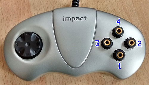
- 1x impact joypad controller (USB Gamepad X6-2OU).
- 4 x 3.5mm socket (e.g. Farnell "126-7396")
- Soldering iron (15 to 30 Watt power); thin solder; soldering flux; de soldering braid; thin wire (e.g. 10 strand 0.1mm), Shrink Wrap (optional).
- Cordless drill with 1mm and 7.5 mm drill bit; Knife or wire strippers; small screwdriver set; Needle nose pliers; Hot glue gun.
2. Make Pilot Holes then Open

With your soldering iron, burn a pilot hole in each of the four push-buttons.
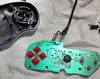
Flip the joy pad over, remove the 5 screws then remove the black rear case to expose the PCB. Next remove the 3 silver screws from the PCB.
Carefully remove the PCB from the case and remove the four clear rubber button covers and discard.
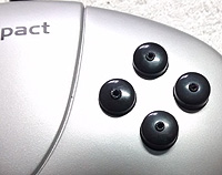
3. Drill through buttons
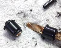
Carefully drill the buttons with a 7.5mm bit. Drill slow and gently, being careful not to catch your fingers.
Fit the socket into the button, perhaps using a pair of pliers to help get enough force onto the socket so it fits flush. Bend the long pole back and forwards until it snaps off to give you more space to fit it.
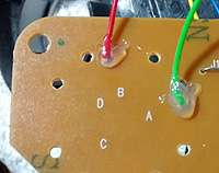
4. Wire up the sockets to the PCB

Cut 4x 14cm lengths of coloured wire, 4x 8cm lengths of black wire and connect them to your four switch sockets. Each socket should have one black wire connected and one coloured. Wire up as pictured above.
5. Sockets 1 and 2
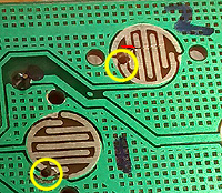
For sockets 1 and 2, it will help to drill a very small hole through the PCB as encircled in yellow pictured left. Wire through the back side of the PCB (as pictured below) and solder to the PCB.
If you accidentally should bridge your soldering across the contact to a ground "finger" contact, it may help to simply cut the finger a little further along (example cut-line in red above).
6. Reassemble and test
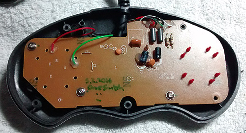

Check your soldering, plug into your PC and test the four buttons and D-pad still works (type "USB" in the PC search bar and then use the "Set up USB Game Controllers" utility. Use the likes of JoyToKey (run in admin mode) and the OneSwitch Pulse system to bring masses more power to this system, including control over the likes of Playstations and Xbox consoles and mouse control.
D.I.Y. Text and images PUBLIC DOMAIN 2014, 2016 - www.OneSwitch.org.uk