

D.I.Y. OOglies
Adapting for disability switch use:
If you're an absolute beginner, I strongly recommend that you follow "The Basic Soldering Guide" - by Alan Winstanley.
SAFETY: Adapting equipment voids the manufacturer's guarantee, and the attempt may cause irreparable damage. Always use adapted equipment under supervision, and disconnect any batteries when not in use. These adaptations are at your own risk. Good luck!
OOglies are wacky toys, that were produced in a variety of designs around the year 2000. They turn up at 2nd hand boot sales, and quite frequently on Ebay.
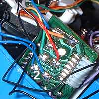
There are two different generations of OOglie, distinguished only by their box and internal circuitry. The version detailed here was sold in Europe only - it has English and French writing on it's box, and more messy internal circuitry (see picture 5.b). The World version has a box with information specific to the OOglie in it and tidier circuitry.
N.B. The 'tidy' World version is extremely sensitive to component damage when soldering. I have a 50% success record with these, failures including complete silence or general madness on the press of a switch. Bizarrely, some have been known to recover after a nights rest! I recommend cutting the wires off as close as possible to the actual head, tail and feet switches, then taping these wires to short lengths of wires pre-soldered to switch sockets. Good luck!
You can use the following steps to adapt most battery toys that operate from push button switches, and few are as difficult as an OOglie. Just make sure that there's room in the casing to fit the socket. If not, you could try bringing a lead out of the casing.
1. What you will need:

- Any OOglie; 3x 3.5mm headphone socket; thin wire (e.g 7strand 0.2mm).
- Soldering iron (15 to 30 Watt power); thin solder; soldering flux; desoldering braid.
- Cordless drill with drill bit 6 (1/4"); knife or wire strippers; small screwdriver set.
2. Peel back hair:
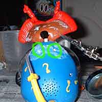
Prise off any head gear to reveal the 2 screw holes (circled in green), and to be clear of the casing join.
Remove all 6 screws and carefully pull apart.
3. Drill 3 holes

Drill 3x 1/4" holes as pictured in the rear casing, making sure that there's room to fit the 3.5mm sockets.
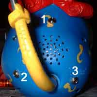
4. Locate Hat switch

Locate the Hat switch (1) and it's 2 wires (black here, but may differ).
5.a. Locate Legs switch

Locate the Legs Switch (2) and it's 2 wires (blue here, but may differ). You may need to remove some mounting screws to get to this view.
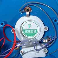
5.b. Locate legs contacts
You can test for the legs switch from the small separate circuit board pictured.
Simply connect the batteries, activate the OOglie by pulling it's tail, then touch the 2 solder points (numbered 2 on this image) together with something metal. This should trigger the same effect as moving the legs.
6. Locate Tail switch

Locate the Tail switch (3) and it's 2 wires (purple here, but may differ).
7. Cut the 3 wires

Expose the wires coming from all 3 switches, by cutting them, exposing the ends, then re-joining them.
Try to do this leaving enough length and room to attach 2 wires that will come from each 3.5mm switch socket
8. Connect sockets
As not all sockets are connected alike, you will need to find which 2 of the 3 contacts you need to solder to.
Attach a test lamp or multimeter to any 2 contacts. Plug in your switch, then press it. If the lamp comes on when pressed you have the right connections, otherwise try a different combination. There's only 3 possibilities.
Solder two lengths of wire to each socket, connecting these to the exposed wires of either the head, tail or legs. Use insulating tape to cover up any bare wire once finished.
9. Reassemble
Push all the wires tidily away, taping them up if necessary. Screw the OOglie back together. Don't glue the hair back in place yet.
10. Test

Put the batteries back in, and test your OOglie. Any problems are likely to be down to faulty soldering. If all seems OK, finish up by gluing the hair down or replacing the head gear.
Text and images PUBLIC DOMAIN 2003 - www.OneSwitch.org.uk